Explanation of the response simulations
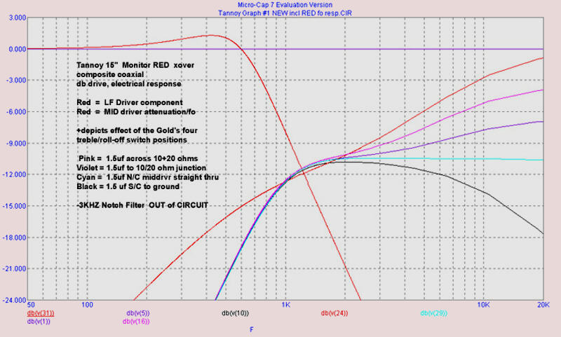
GRAPH #1
is the fixed Monitor RED lf/mid (the two red traces) response overlaid on
the Gold's switched mid responses, without the 3khz filter in circuit for
any of the traces
What is immediately apparent is that the choice of lf/mf crossover
frequency f-3db's (both less than 850hz) are almost symmetrical.. for the
Monitor RED's electrical crossover response (in graph #1) which are the two
red traces. (the difference in hf response between the red/gold xover is
obvious, with Red proponents claiming a 'better' hf response as a result of
the depicted response for the earlier driver).
The Monitor RED does not use an inductor for the highpass section, only a
simple r/c pad and capacitor sets the
attenuation/sensitivity/preemphasis and hp filter function.....
this is approximately matching the attenuation level referenced for the
Monitor Gold's 12db/octave l/c/r hp filter.
The fixed 'rising with frequency' electrical
drive response from the crossover is necessary to achieve a reasonably
smooth Acoustic response, in fact for both the RED and GOLD mid/hf
drivers....and is not at all unlike the r/c pad corrections necessary for
the most modern implementations of Biradial, cd, and Waveguide horns.
Accordingly, Tannoy have named the Gold's (mainly variable boost)
switch 'Treble Roll-off', although one can plainly see that the switch
function (electronically) is to provide varying and lesser degrees of
mid/hf boost, for two of the switch positions, with one being flat/straight
through (1.5uf o/c)..... only the last switch position giving an
electrical Treble Roll-off characteristic, in fact.
As well, the graphs were made using pure resistance instead of the actual
driver impedance models, which impedance models only serve to make
the hf response look 'worse'...as in a little
more exaggerated.
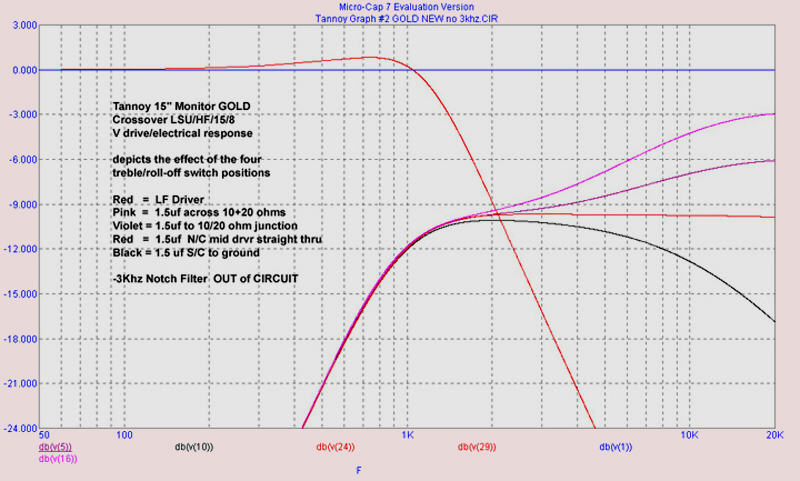
GRAPH #2
It can be seen that the Monitor GOLD in graph #2 uses an overlapping
electrical (Assymetrical) response to achieve best summation at the acoustical
crossover point, and has quite similar hf sensitivity to the earlier driver
(the driver electrical responses, for lf f-3db is about 1,5khz and the hf
f-3db is about 880hz, result in Tannoy stating the acoustic crossover result
to be 1khz).
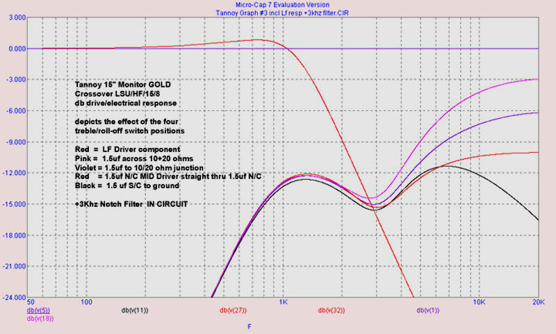
GRAPH
#3
is as #2 but includes additionally the effect of the 3khz filter, implemented
straight with notch depth reduction due to the 0.82mh inductor's internal
resistance of about 11ohms.
Additional information
What is not shown is the additional
acoustic output which results from coincident f-3db acoustic summation .
-the electrical overlap necesary for the drivers which results in this for
the Tannoy driver's must be kept in mind when duplicating the curves with
an active crossover.
It must always be remembered that it is the electrical drive depicted (not
the acoustical response) by the curves shown.
Smooth acoustic response results from the gently sloping natural rolloff
of the early Tannoy DC midfrequency unit's, the increase in db/spl at the
acoustic summation point and the 3khz resonance filter notching, together
with the difference in lf/mid driver sensitvity which is indicated by the
graphs as well.
This is not unlike the high frequency coreection necessary to achieve the
same thing in a modern cd, biradial, or waveguide horn, but for different
reasons, and with different results.. in that the modern horns exhibit a
uniform power response, rather than mainly axial performance of the
exponential/tractrix types.
The graph colour codes are corresponding to
the treble rolloff switch wiring colours depicted on the 1967 Gold's
crossover listed for years already on Hans' website
http://www.hilberink.nl/speaker1.htm .
However, there are examples of different colour assignments for the Treble
rolloff switch given on other sites.
Quite the opposite situation is happening for the so-called Treble
'Energy' (shelving) switch positions, where wiring colour is uniform, but
with different inductance values being assigned to the same colour. (the
'Green' wire is 3mh on some crossovers, while on others it is 4mh).
To
avoid confusion as to the expected f-3db point resulting from the
different values of the tapping, it is correct to describe this tap wrt
it's function (highpass filter winding section of the Autotransformer).
There has been past discussion, going back
years, concerning the alledged "Mystery 50 ohm" resistor.
It's function is damping trim, enabling adjustment of the nominal
12db/octave slopes to more closely approximate the ideal Butterworth
characteristic slope, given expected production variation wrt the
theoretical guestimations of coupling coefficients in the practical
autotransformers, which 50 ohm resistor is in parallel with an existing
45 ohms across the autotransformer represented by the10ohm+20ohm+ driver
impedance. (one of the Autograph xover's uses 100 ohms for eg).
(treble boost at two different frequencies, is provided by switching 1.5
uf across either or both of the series resistors (10+20ohm) with phase
delay/treble rolloff by s/c the1.5uf to ground, the 30 ohm total series
resistance and switched 1.5uf then forming a simple low pas filter)
.
The 50 ohm damping resistor is more optimised for the Values corresponding
to the Yellow tap on the 1967 crossover circuit, and is a compromise wrt
to other tap values otherwise used in switching different midriver
shelving levels. (termed 'treble energy' taps by tannoy). Even though
the total inductance values of the taps are quite close (for the 3mh
green+1.2m yellow...... vs 4mh+0.5mh for the 1967 circuit on Hans'
Tannoy site
http://www.hilberink.nl/speaker1.htm ), the mutual inductances
corrsponding are quite different.
Note that the 50 ohm is not switched across
the highest impedance tap (red wire)... the 10 ohm and 20 ohm series
resistors with the mid driver impedance across this tap provides more than
adequate damping, alone.
As well as affecting the slope, altering the value of the "50ohm" resistor
necessarily affects the attenuation of the mid/hf driver, which is also
quite audible. The beauty of an active crossover is that these circuit
operations are isolated from each other by unity gain buffers, so that
changing one will not alter (confusingly) the other parameters at the
same time. .
The value of the 50 ohm resistor was
optimised to 56 ohms by constructiing an
12db/oct butterworth active filter in parallel with the passive filter in
the simulator and simply superimposing the two output graphs, while
stepping the value. The value was selected for the passive slope to match
that of the idealised Butterworth for one of the
Autotransformer/inductance models.
Taking the value to 30 ohms
*overdamps the
response, in fact dropping the mid driver response slope ~1khz, and so
spoiling the acoustic summation through crossover that tannoy intended
originally....
*If the values are those values depicted on the 1967
crossover (on Hans' site, see
above link), for the k values guesstimated for the ideal
Autotransformer modelled, for eg.
But if the inductance is 3mh, wirh the
yellow tap at +1.2mh a 37 ohm value is pretty well smack on, slope wise,
for the optimised 'k' values used for THAT autotransformer model....but
with of course increased attenuation around the 1khz point for the mid
driver alone, Otherwise this quite definitely overdamps the response.
The 3khz filter is a simple L/C/R series
trap (3.3uf+0.82mh) directly across the middriver voice coil. The Q or
sharpness of the notch is dictated by the internal winding resistance of
the 0.82mh coil (820uh = 0.82mh) of approximately 11 ohms, subsequent DC
drivers used an additional amount of series resistance to reduce the depth
of the notch, and some owners have made this an adjustable 50ohm pot.
Note that if one is running the middriver directly from an amplifier, in
using an active crosover, there will have to be some additional resistance
introduced in series with the trap/mid driver, or this type of filter
cannot work as intended. (about 10 ohms is sufficient).
To duplicate a given original
autotransformer, one has to first determine the value of the tap the 6.8uf
capacitor is connected to... and then that of the corresponding tap above
this which gives the desired attenuation.
As well, one has to use the same core material and former, and wind the
same dia wire/coil in the same spacing, sections and layers as the
original, in order to achieve the same mutual inductance and coupling and
leakage inductance and wibnding capacitance between the taps to achieve
the same sound, all of which affects it as does the characteristics of the
core.
Normal production variation in the practical crossover components, and the
idealisation of some parts in the computer conspire to mean that any given
xover may not measure the same as any other xover. Even individual drivers
from the same run's can sound slightly different, too.
For
active crossover users, it would be pertinent to make, and include at
line level in the preceding the power amplifier, a high impedance
version of the frequency correction circuitry
which the crossover uses after the auto
transformer, when using active crossovers the corrections needed by
the drivers are the same regardless of crossover
type.
To run the correction at line level, it is usually only necessary to make
the 10 ohm + 20 ohm R's into a higher impedance 10k + 20k and the
cap value to 1,5nf (1500pf or .0015uf allee
same) where the volume pot following is 15k in
value, for example. this maintains the same time constant for the
r/c values and so the same frequency corrections as
Tannoy spec'd their
passive crossover for.
Remark
concerning
the RED's impedance
Ihe RED's sensitivity figure quoted as 93db
(rounded off) is resulting from only a half watt as a result of 15
ohms.......... while the Gold at 94.5, (or rounded off at 95db)
is
resulting from a full watt due to the impedance of the lf section being 8
ohms... both from 2.83 volts, and w=e^2/r always....
Depending on the frequency range warbled or
averaged, it would appear that the Red/Gold composite coaxials have very
similar sensitivities, actually....... even the series resistor of 30 ohms
is the same (10ohm+20ohm) and for both reducing the sensitivity of the 15
ohm common impedance mid driver down to exactly the same levels, with the
only difference here is that the Red's fixed hf boost is resulting from a
2uf rather than 1.5 uf cap in parallel, so ends up with proportionally
higher hf boost than the Gold at the frequency extreme above 10khz.
Software used in this
article
It is indeed an expensive, and sometimes fruitless exercise to buy
components on a what if basis, and on the other hand it has been argued
that mere mortals cannot justify outlaying $7,000 for a circuit
simulator to readily graph the results without a chart recorder, scope
or soldering iron in sight.
However, microsim have released a
student version of the software, FREE, which will do everything
"crossover-wise" valve and ss, and even some full SET amps, as it
handles up to 50 passive/3 active components.
The model i use in Pspice (and in Microcap allee same) is quite
similar to the last one listed in the paper above as example 8.
However the beauty of the latest version of Microcap 7.2.4, (even in
the Freebie student version) is that all one needs to do is define the
Autotransformer model for the inductances (for example 4mh plus 0.5mh)
and dial in any coupling coefficient between
-0.99 and 0.99.
John Ridley
johnridley@tpg.com.au
© Copyrights Hans Hilberink &
John Ridley,
last update: 04-02-2004-Vc.