|
LUXMAN
vintage
audio |
|
LUXMAN
vintage
audio |
Luxman C12 control amplifier, M12 & B12 power amplifier
General:
This C12 pre-amplifier, or control amplifier as Luxman likes to call it, and power amplifier M12 set was produced between 1977 and 1981.
They are part of the "Laboratory Standard Series" just as i.e. the B12, T12, T14 and the L10, L11.
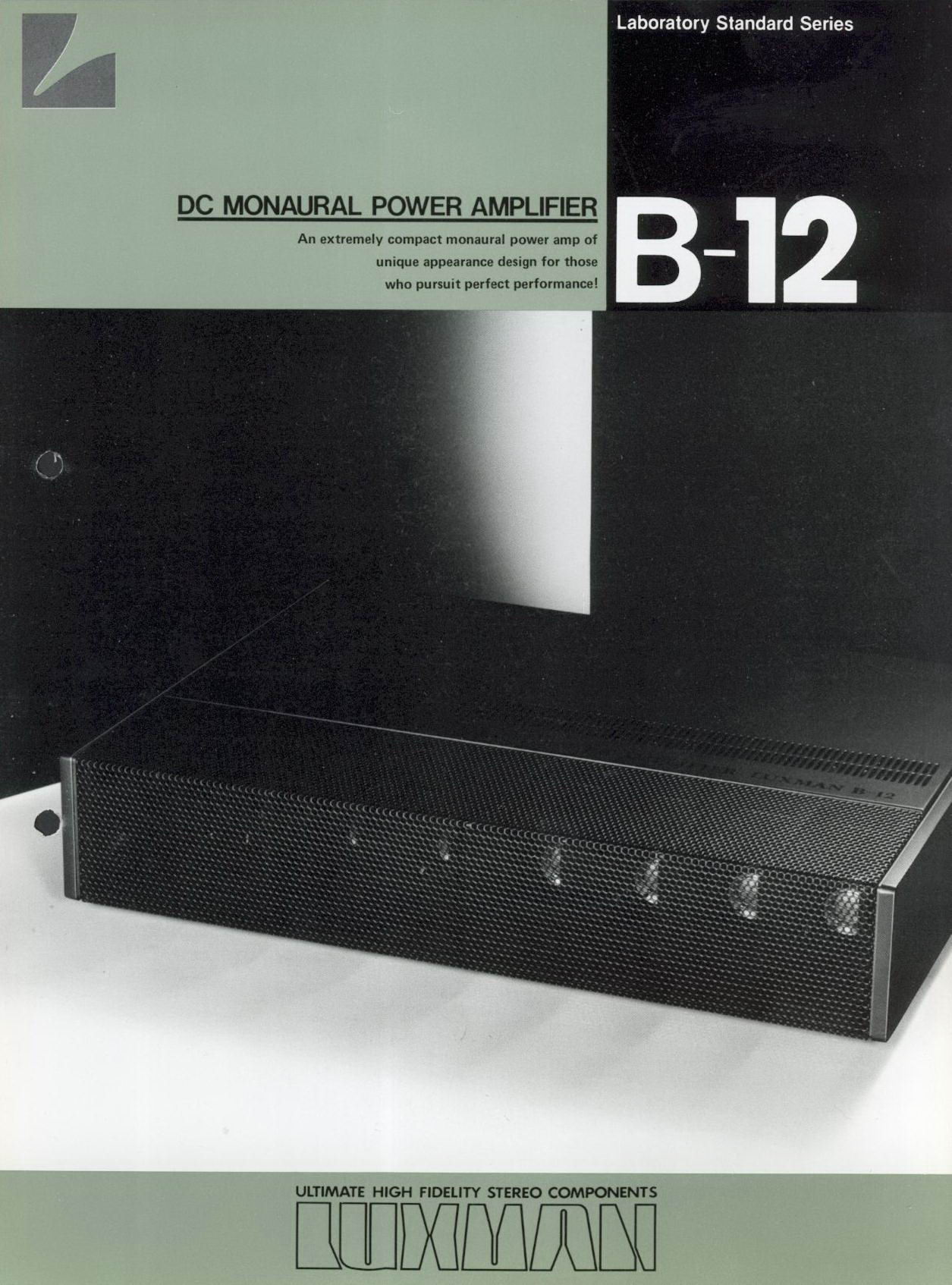
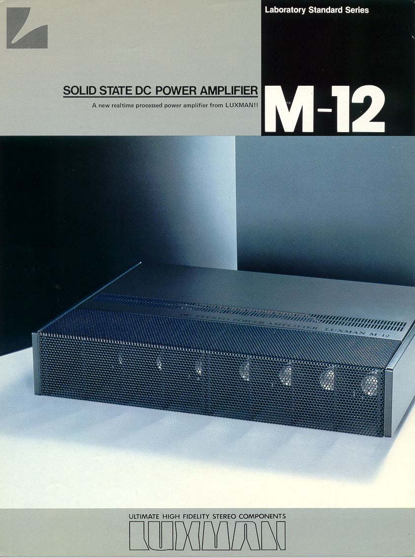
The M-12 is a stereo amplifier and the B-12 is a monoblock.
The amps are based on the Luxman Realtime-Processed DC circuit.
C12's and M12's were "customed" by Lux, customed meaning that the C12's and M12's were limited editions
and that Luxman used customized electronic parts for this series, as you can see on below photos.
Special features:
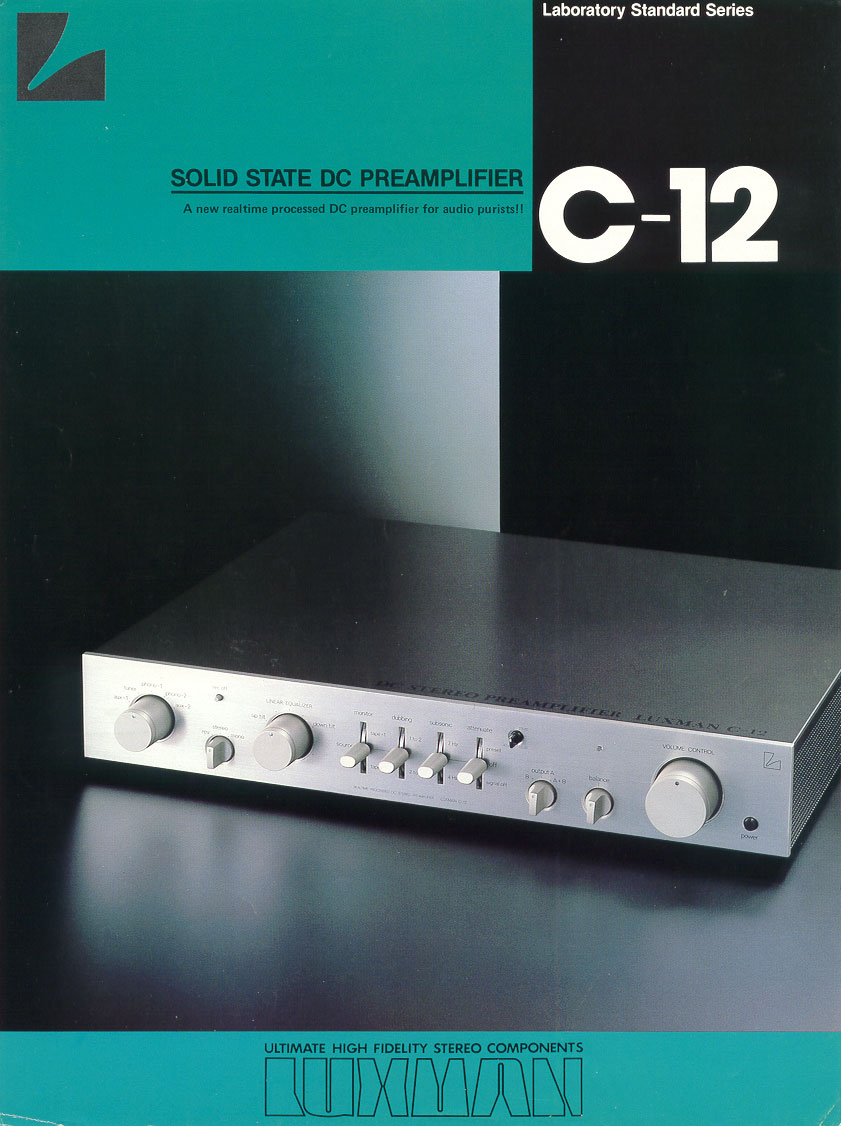
C12:
The pre-amp section of this set, the C12 was remarkable because of several features.
The Luxman C12 pre-amp is a full DC coupled class A design.
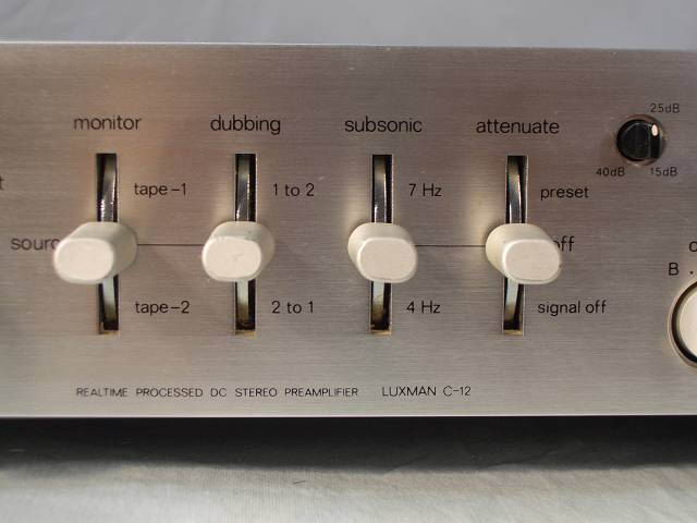
The C12 futures:
Dual selectable subsonic switch.
Full tape dubbing facility.
Selectable stageless preset attenuation with signal off setting.
Separate stereo headphone amplifier.
The C12 employes no tone-control, it does however have a "Linear Equalizer".
Below is explained what it does and why its better than traditional tone control:All the program sources available are not always perfect. Record discs, cd's and tapes, as a program source, are liable to have a slight deviation of linear nature depending on the manufacturers. For example, all recordings are equalized in accordance with RIAA standard, but its quite common to encounter variations in overall tonal balance from one recording to the other. Also, differences in listening environment and room acoustics often require a subtle degree of tonal compensation that conventional tone controls cannot correct because of their wide range and overlapping characteristics. The "Linear Equalizer" control provides a form of tonal compensation especially intended for this sort of tendency. With the control in its mids position, flat frequency response is achieved. Switched to the "up--tilt" positions, the entire response curve is rotated on a 1 kHz axis so as a linear increase treble response while simultaneously decreasing bas response. Conversely, selection of one of the "down-tilt" positions rotates the response curve in a clockwise direction, providing a gradual decrease of treble response and simultaneous increase of bass response. Degree of slope for either positive or negative settings has been carefully preset, and the overall response maintains complete linearity from 50 Hz to above10 kHz, unlike the curvature in response normally associated with ordinary tone controls. Specifically, when the control is turned to the max "up-tilt" position, it will decrease bass and increase treble by 2 dB at 100 Hz and 10 kHz respectively. Selection of the max "down-tilt" position will decrease treble and increase bass by 2 dB at the same reference frequencies. At the center of the rotation, components which consists the Linear Equalizer are all by-passed to realize flat frequency response. The control is inserted in the flat amp circuit and is effective on ALL program sources. It introduces no increase of harmonis distortion in any of his settings because of the inherently linear nature of this circuit.M12:The Luxman M12 main-amplifier is a full DC coupled class AB design. It has generous output power from 80 to 90 Watts per channel RMS, up to 150 Watts max. peak power capability per channel together with extreme low distortion levels. Protection circuit and special features are very good.B12:The Luxman B12 is a high power version of the M12 but in monobloc issue, for stereo you need 2x B12. It has generous output power from 150 Watts per channel RMS, up to 250 Watts max. peak power capability per channel together with extreme low distortion levels.
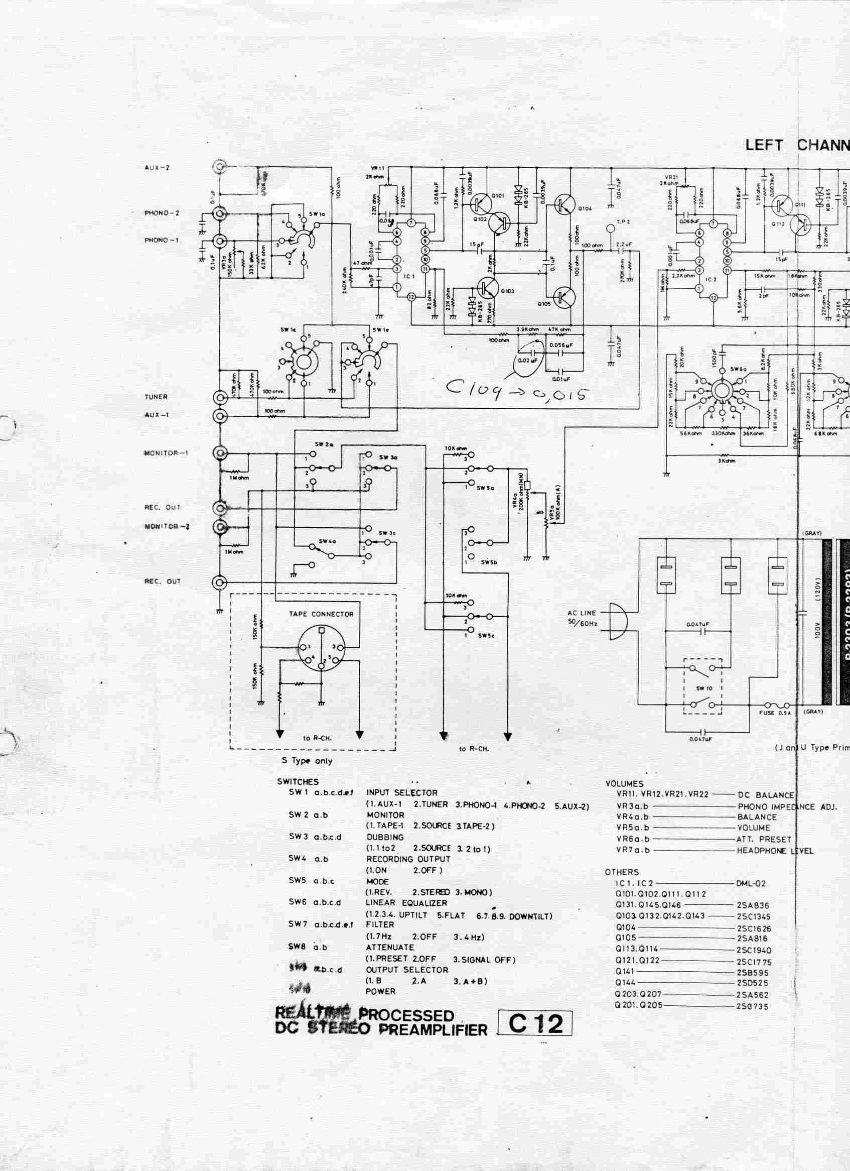
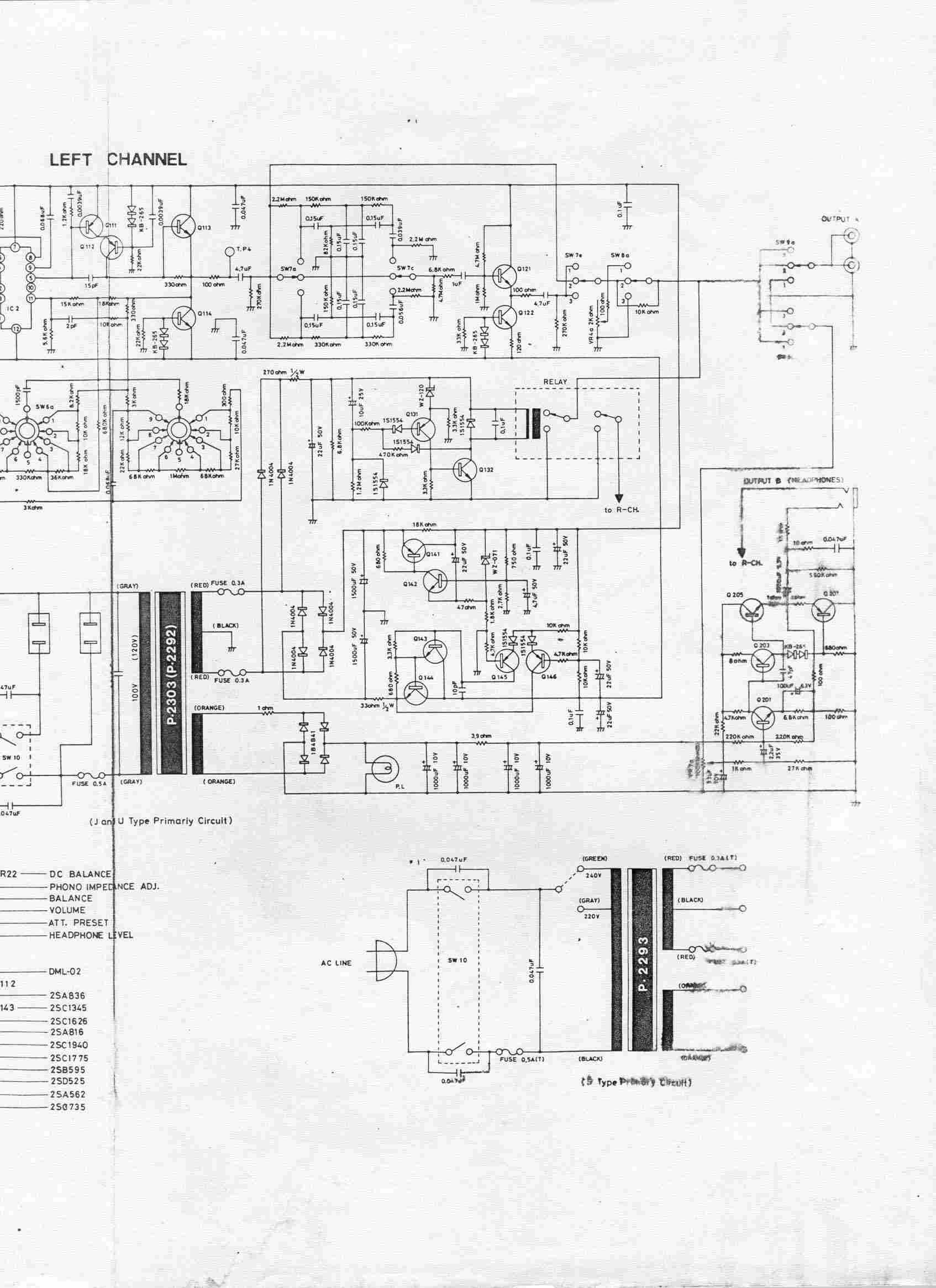
Schematic:
C12 schematic diagram:
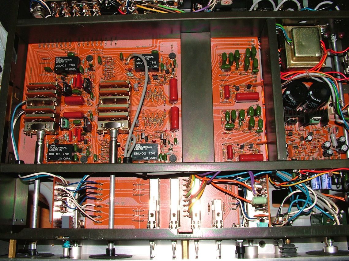
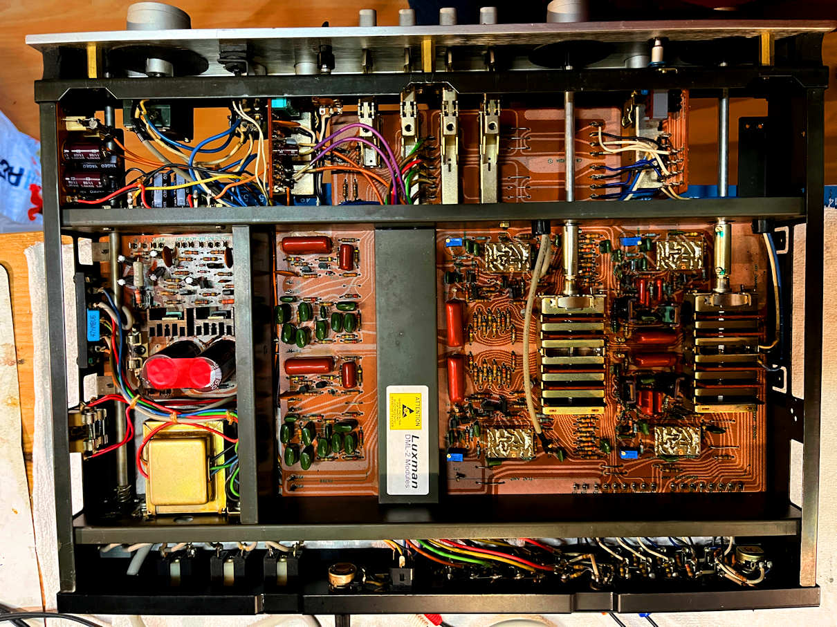
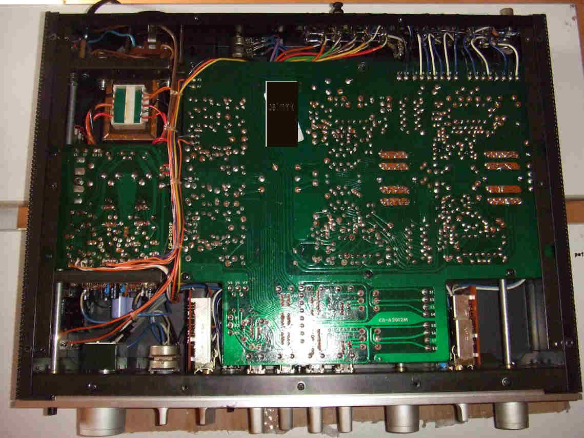
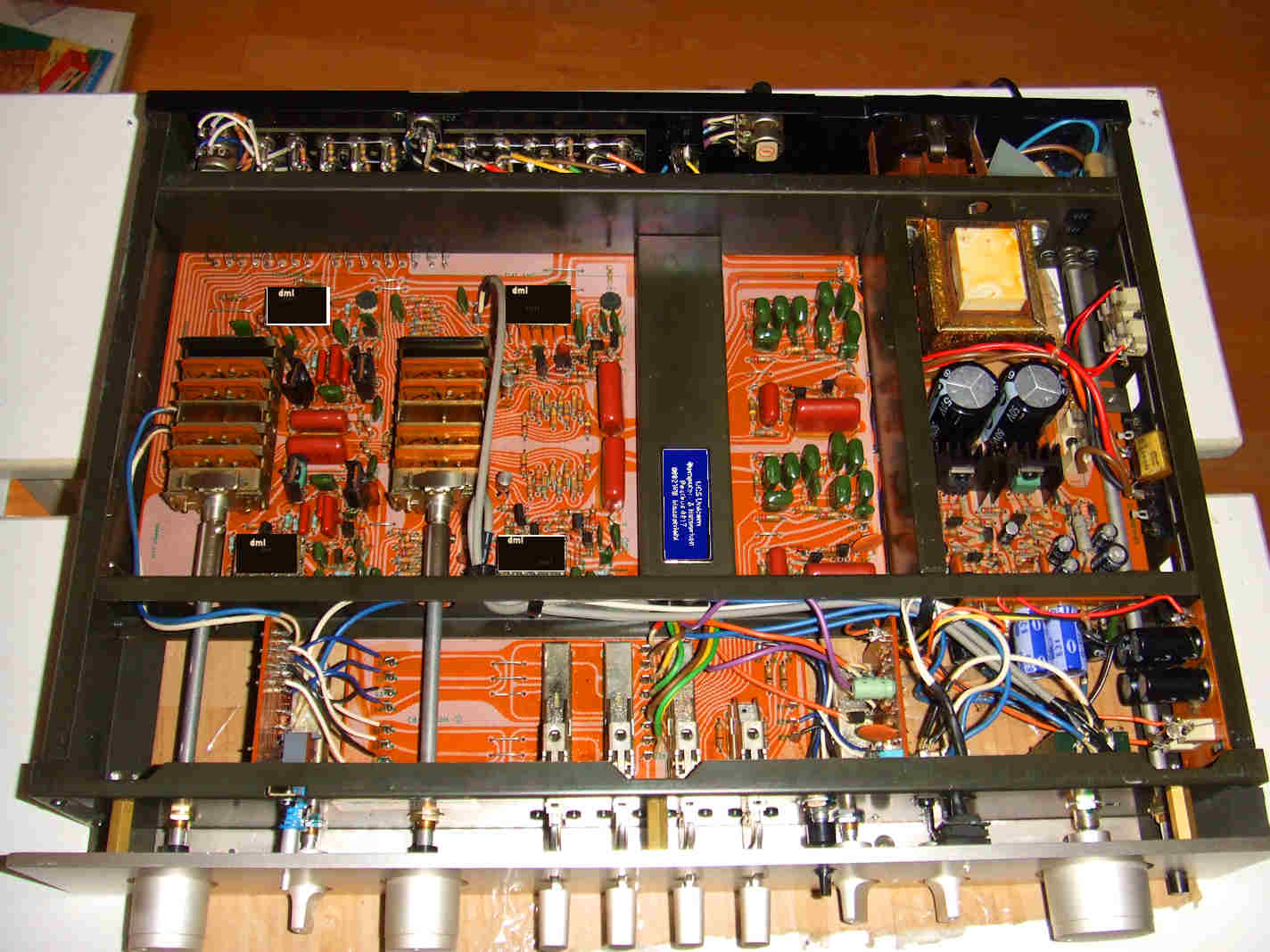
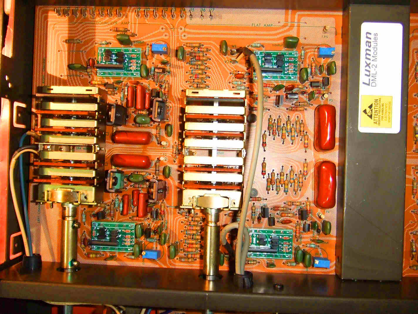
Luxman C12 interior, not updated. Old DML-02 x4 that are broken. This C12 produces noise and hiss. ^
A tech man used these in the power supply, but this is not right, it blocks the airflow in the power supply unit and has to be corrected.
Also the 4 pots have to be exchanged for ten-turns ^
Old DML units that are ok after full restore, no need to replace ^
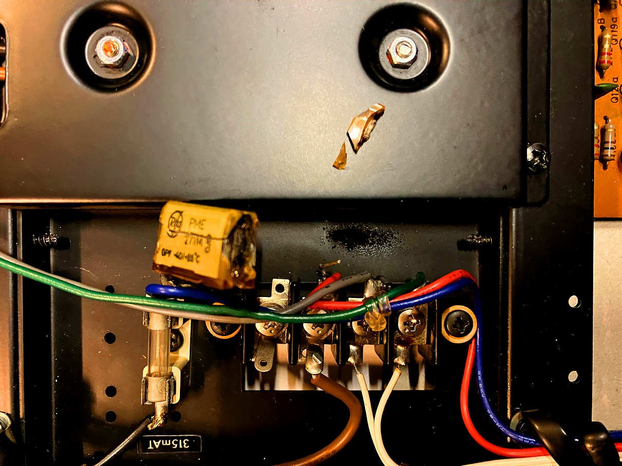
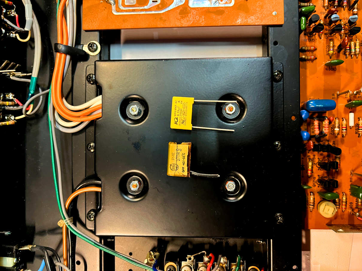
Exploded power line cap ^
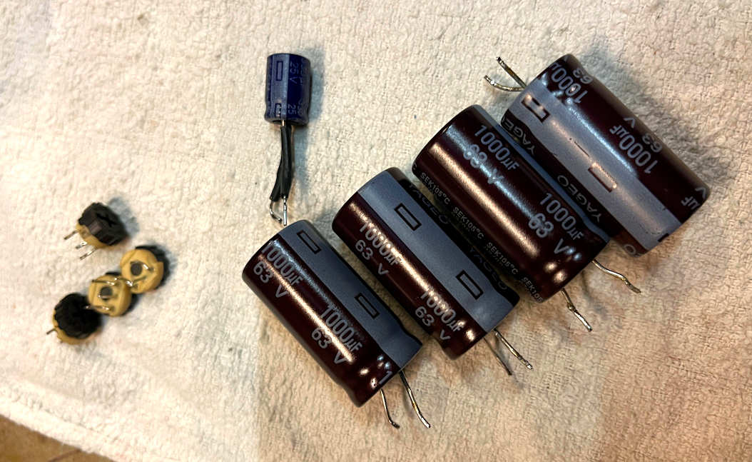
Here the new cap for replacing:
Modifications:
SERVICE WARNING:
When you service the Luxman M12 amp you should be aware of the fact that the power
supply capacitors keep the full +/- 55V = 110 V supply voltage on them when the amp is switched off,
even when completely taken off the mains supply and even after being weeks out of use.
These caps should be discharged by qualified service personel the proper and safe way with 100 Ohms resistors.
If you fail to respect the full & correct manual discharge of the power supply caps,
you will almost certainly damage the power amplifiers and possibly all output transistors,
also improper discharge of these caps may be dangerous for your health.
The output transistors of the M12 are out of production and not sold anymore and
there is NO replacement transistor that is suitable and gives the same exceptional
performance of the Luxman M12 amplifier.
All M12 amplifier models with different output transistors may sound well,
however do not meet the original M12 specs of Luxman.
Schematic diagram of the Luxman M12 in PDF
Click here to goto the DML replacement page of the Luxman Vintage Website.
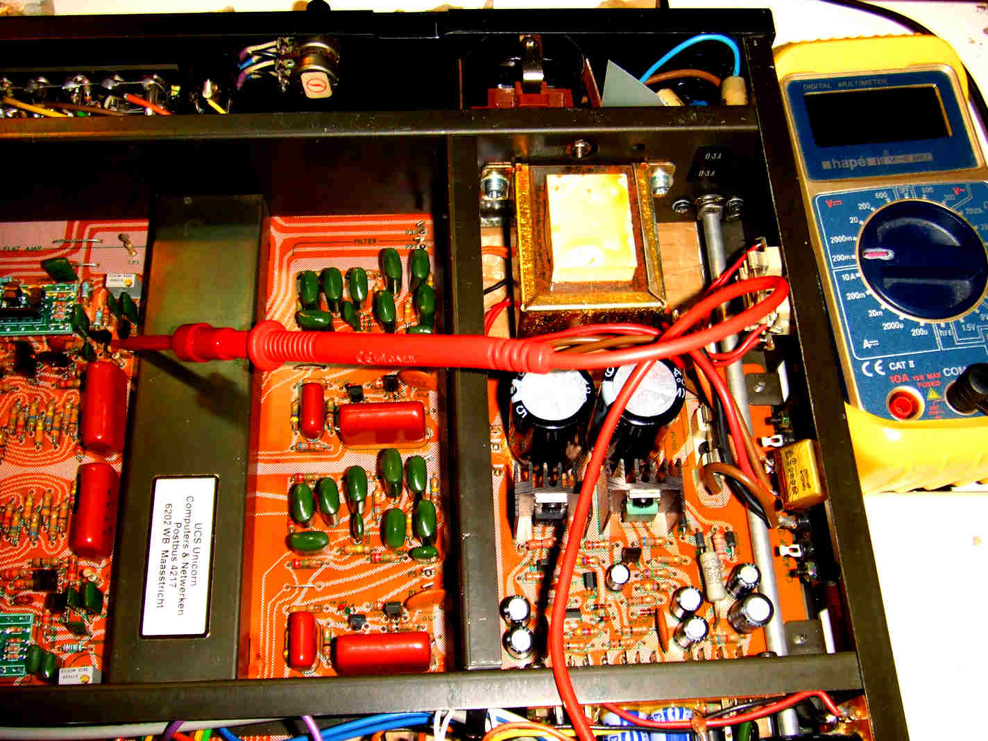
Inside the M12: two torodial transformers, two power sections, all completely mono x2. ^
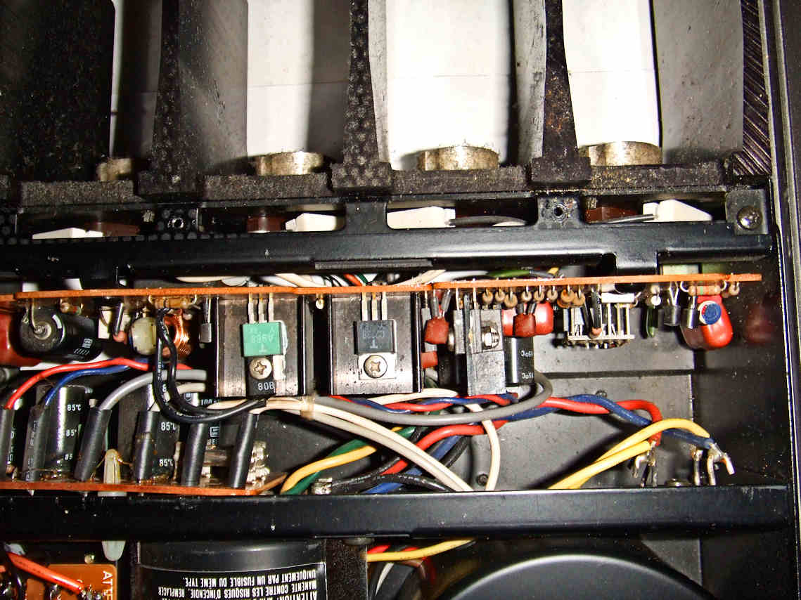
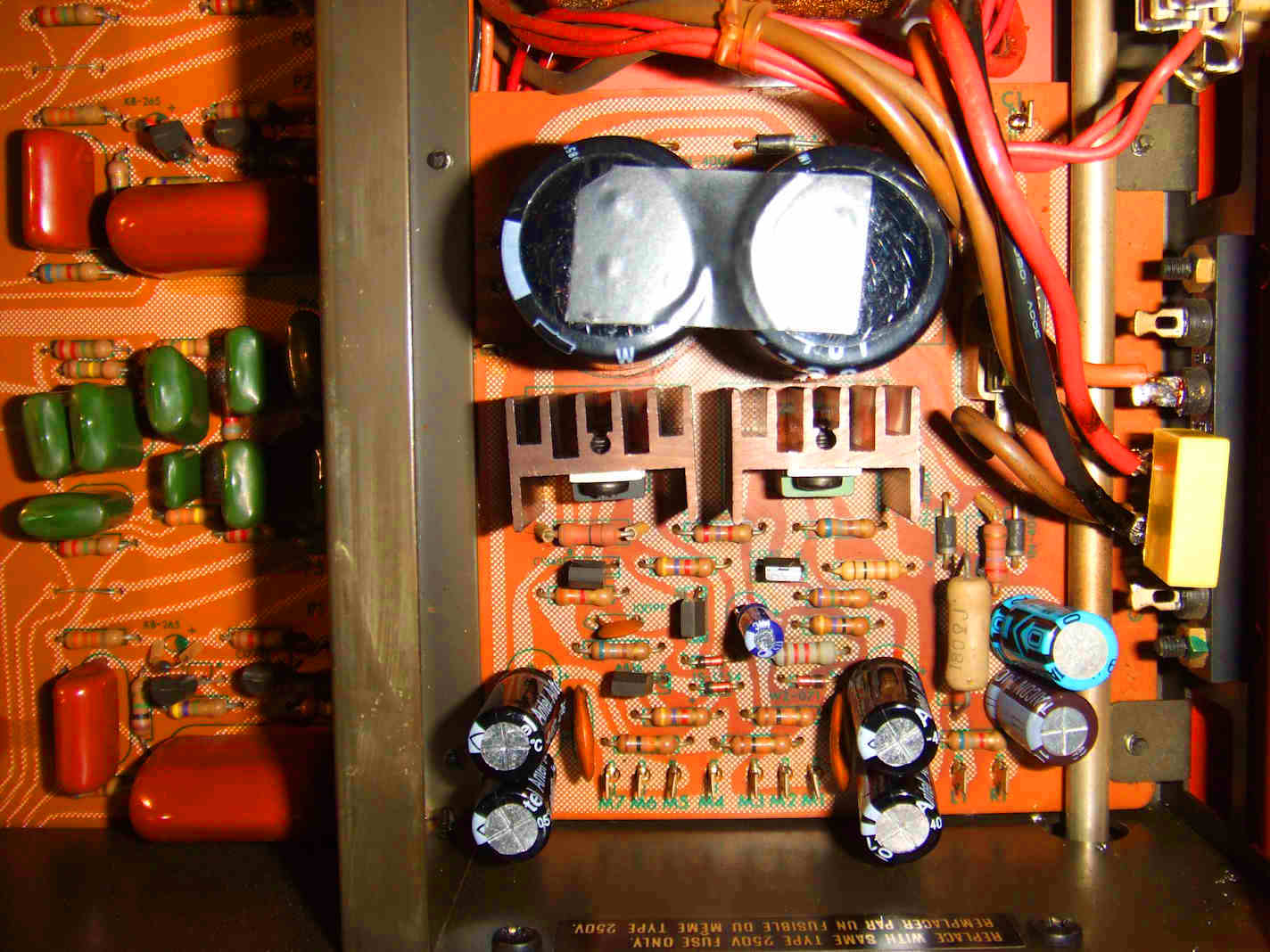
The power amp section: Right channel. ^
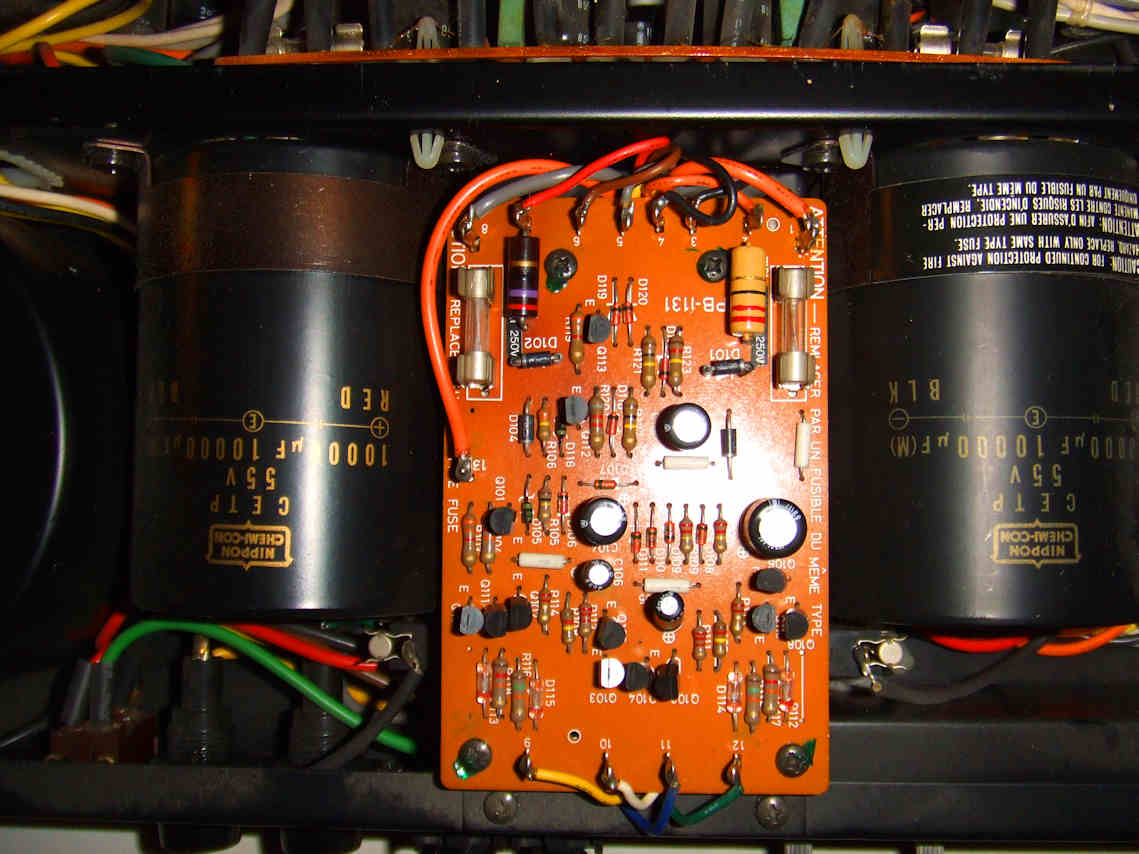
Huge Electrolytic Caps of finest quality and a additional control board. ^
User manual:
click here to download the user manual in zip format.
Click here to goto the DML replacement page of the Luxman Vintage Website.
Luxmans DML's:
The DML ic's employed in both units are often the cause of problems and need to be replaced by the new DMLs as presented on this website.
Of the replacement DML-01 there are 3 different versions known.
Using version 3, as presented on this website, for replacement of the original DMLs is preferrable.
Of the replacement DML-02 there are 2 versions known.
Using version 2, as presented on this website, for replacement of the original DMLs is preferrable.
Use the on this website presented replacements for extended life of your Luxman, read the details of this DML issue:
Click here to goto the DML replacement page of the Luxman Vintage Website.
The schematic diagram of the DML-01 version 2:
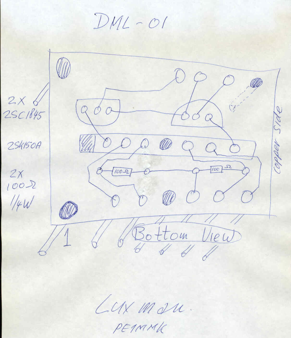
The pcb layout of the DML-01 version 2 is below: V
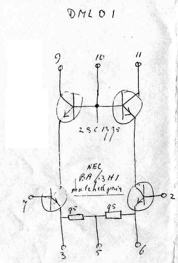
The schematic diagram of the DML-01 version 1 is below: V
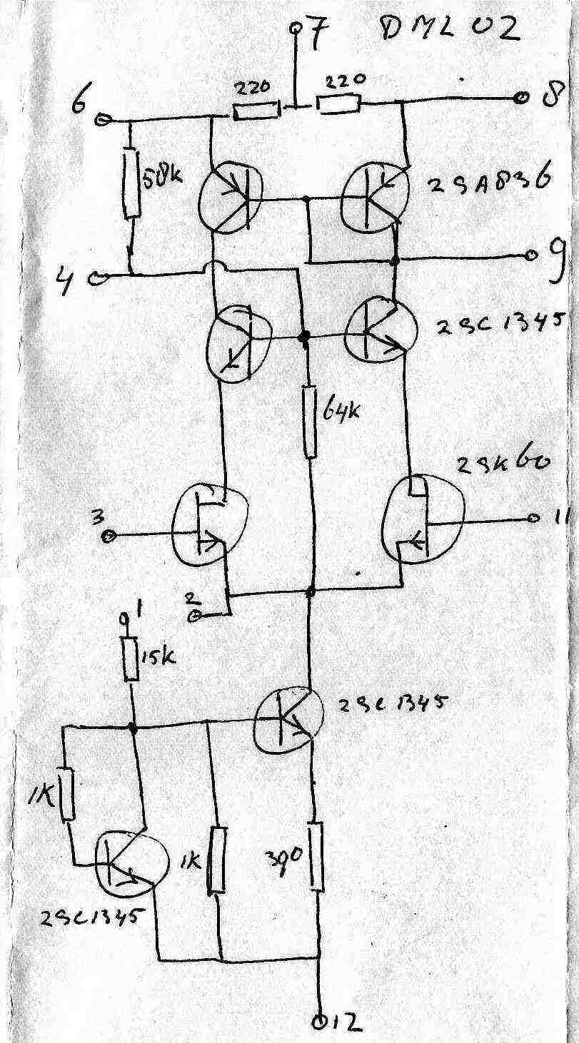
Below the schematic diagram of the DML-02 version1: V
Exchanging the DML's:
Click here to goto the DML replacement page of the Luxman Vintage Website.
Desoldering the old broken DML's ^
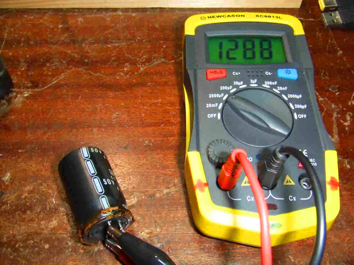
Measuring the old power supply caps, still 1288 µF of 1500 after >30 years, not bad, but need to be exchanged. ^
Exchanging caps in the power supply ^
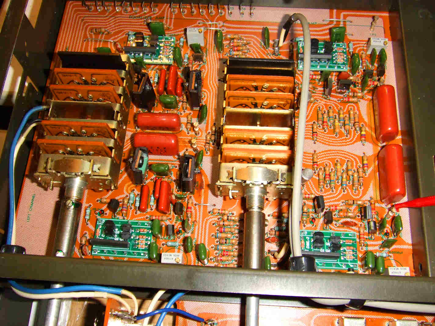
The little black boxes are the DML's that should be exchanged, ^
Our new designed, made in USA, new DML's inserted and the new pots as well are soldered in its place: the best exchange there is ^
Yet another C12 DML exchange: Looks better this way not? ^
Setting the DC offset to 0 Volts with a DVM at 200 mV range at all four test points ^
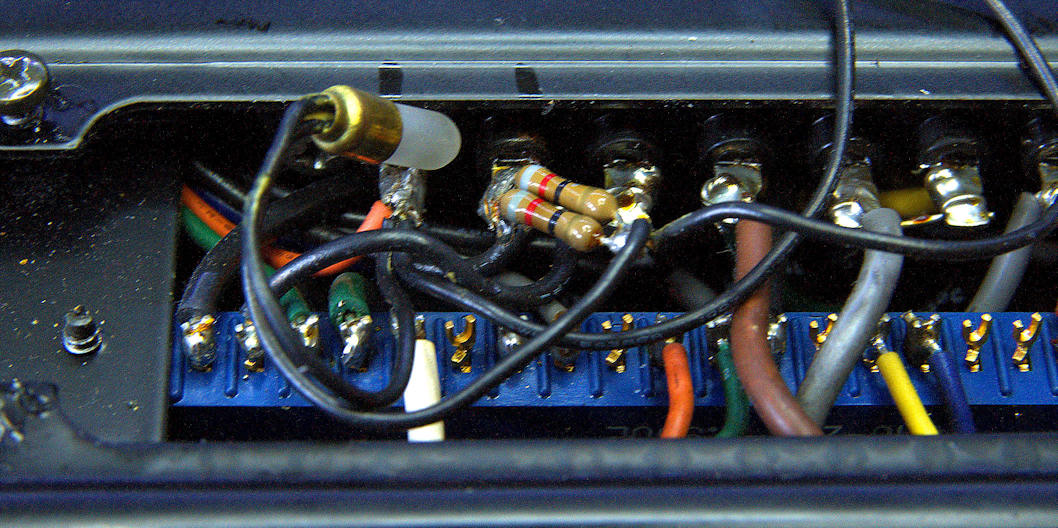
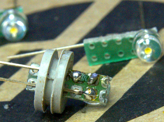
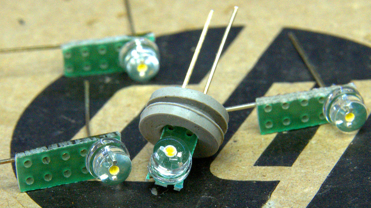
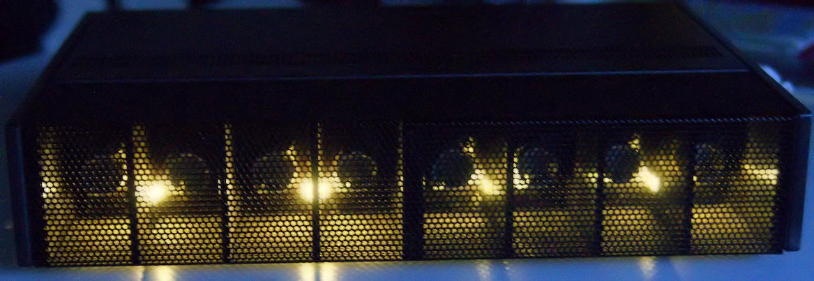
M12 pilot lamps exchange:
You may exchange the broken pilot lamps by LEDs. Tjerk S. sent some photos showing how he did the exchange:
The broken pilot lamps, for the correct LEDs brightness you may change the resistor value used for the lamps.
Great results.
Sound:
These series of "High Quality" audio components soon got legendary of their outstanding build quality and excelent sound quality.
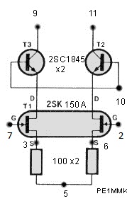
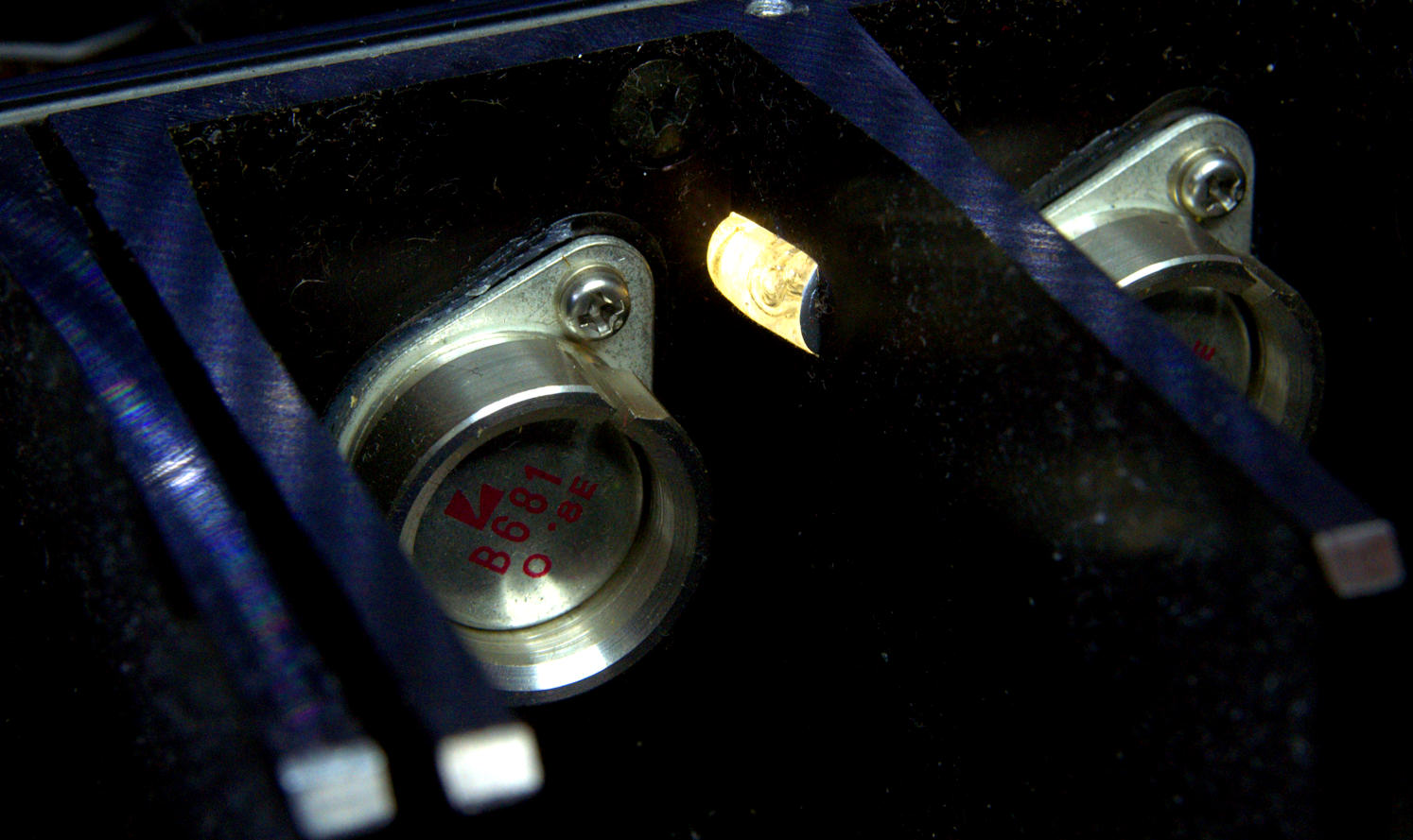
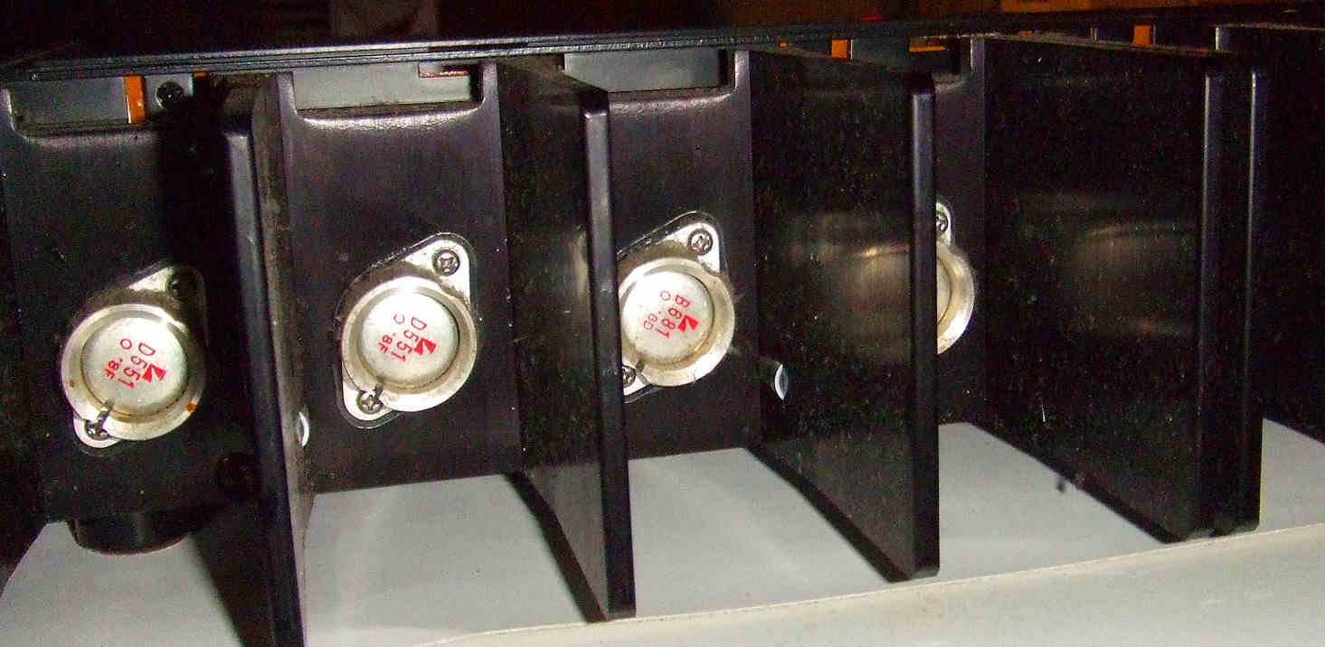
The custom made power transistors of the M12, with the Luxman logo printed on them, this is what "customized" means..
Click here to goto the DML replacement page of the Luxman Vintage Website.
![]()
![]()
Copyrights: Hans Hilberink - PE1MMK - ©1995 - Last update: 05-05-2025. Pilotlamp photos: Tjerk S.