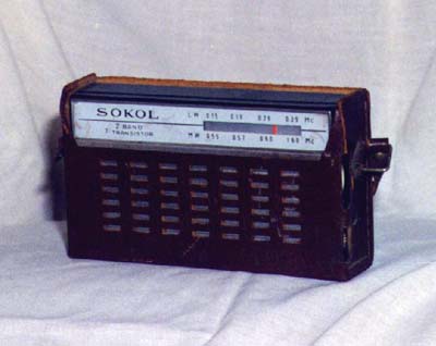
model Sokol 402
Pocket radio made in USSR - 7 USSR germanium transisitors, 1 transistor is encapsulated in a metal shield-can. The purpose of this is unclear because it is a IF transistor, I cannot imagine that it is done to keep the transistor away from strong external electromagnetic fields, the only reasonable explanation is that the transistor has a high amplification factor and is unstable in its function, the shielding sould improve stability of the stage? - reasonable sound and good reception - MW / LW - 9V and adapter supply.
Model Sokol 403
This radio looks different from the 402 but has very similar electronics.
Click here to see more info and the schematic diagram of the Sokol 403.
Micro radio model Cosmos

Made in USSR in approx 1974 - the HF transistors are traditional big USSR transistors, but the LF transistors are smaller than the usual used ie. in the Sokol above, they are constructed for the use in micro equipment - in this radio something caused the death of the oscilator transistor and the first IF transistor, I replaced them with European ones and now the radio plays again - The wires inside are weak and the whole construction is a bit strange, as if a team of engineers wanted to realize this radio in two opposite ways, some parts are well constructed and some other parts are not to be used in a micro radio, also this radio has an antenna input, but there was another not connected antenna input inside the radio, as if the workers who assembled this radio put in two by mistake and only connected one. Overall this is a well constructed radio with a typical microradio look - Supply by 2 1,5 V button cells for 3V.
Do you have some USSR spare transistors to bring this radio in its original state?
model Etude 2
Very thin radio approx 1" or 1,5 cm thick - radio with small speaker in cabinet - the radio has 4 conventional USSR Germanium and 2 ultra small USSR micro transistors inside. It has LW/MW and supply is 1 P cell for 9V. Nicely built radio. Strong cabinet.
model "Junga" (i-onga)

USSR 10 transistor radio without any IF section. This is a kind of reflex reciever with extensive AF amplification. No (zero: 0) IF coils are used, only RC-filters are used in the RF section. This is a LW/MW version with only 2 coils on the ferrit rod as antenna. The RF section has orange coloured USSR Silicon transistors and the AF section has the well known big-can gray-silver USSR Germanium transistors.
model Alpinist 405

Nice radio with MW/LW from 1972. It has 7 USSR transistors, 3 silicon and 4 germanium. The final power transistors are quite big ones, they must be able to deliver 1 Watt to the speaker. It is a very traditionally built radio. It plays well. Supply by 6 "C" cells for 9V. Very odd is that the final power supply capacitor of 500 uF is not on the pcb, but in a special little box, made on the bottom left of the cabinet. Look at the pic below at the arrow, you can also see the nice big power transistors of the final stage:
You can have a look at Gerard's site for additional info on this radio: click here.
©Hans Hilberink PE1MMK Radiomuseum 1992 / 31-08-2005.


