Transistor Amplifiers continued
12![]()
How to setup a power amplifier the right way?
Here are some ways how a good
chip & discrete amplifier is to be set up.
Look at the pictures as they speak for themselves.
Do you think the below picture shows the right way to setup an amplifier? Well I do not!!! Look at my pictures on this page to see how its done the proper way.
This amplifier below is incorporating the Andre Schmeets 2 x 250 Watts design
as discussed on this website in "Transistor Amplifiers" pages 5 and 6.
The power amplifier in functional configuration.
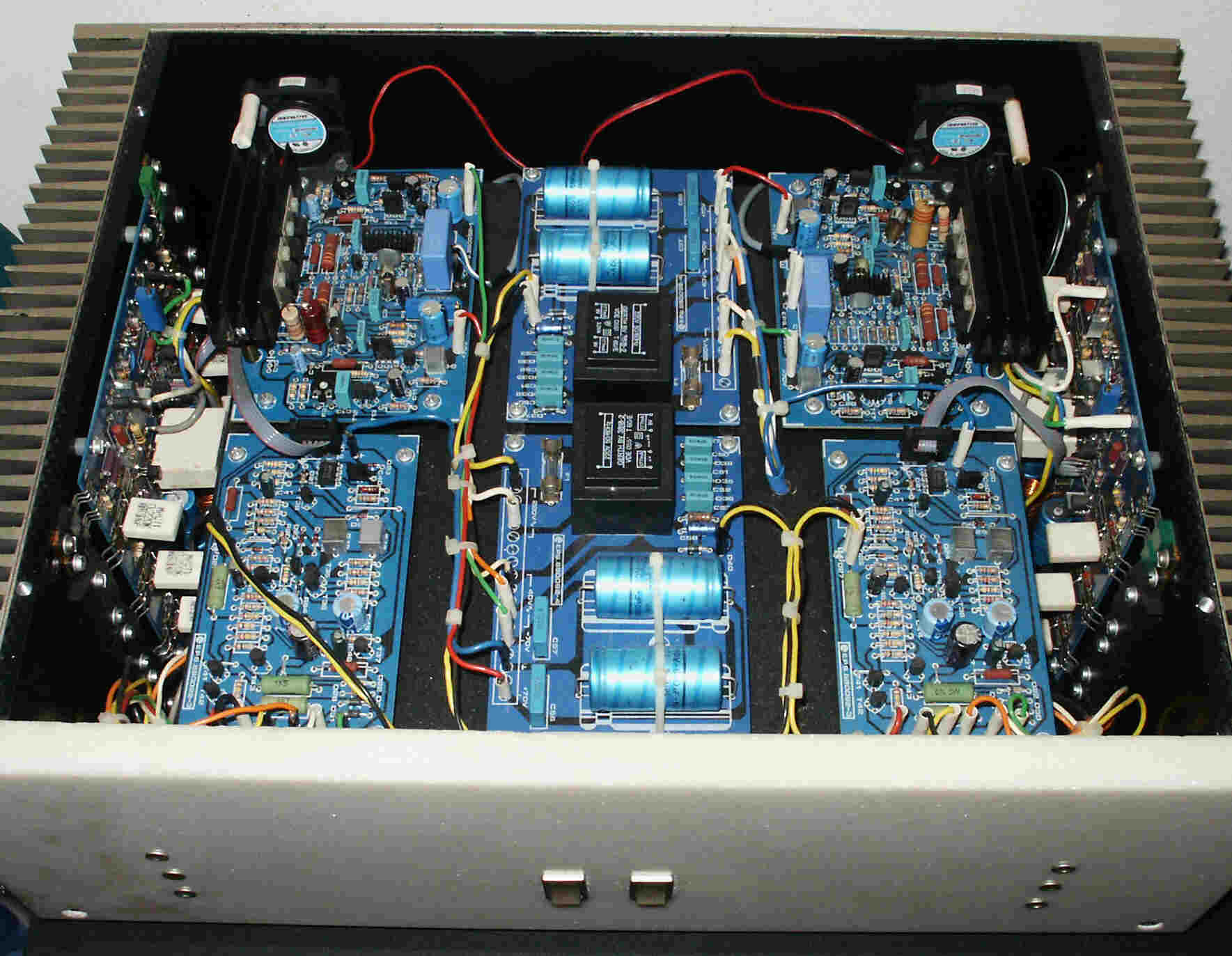
The transformers, rectifiers and 500000 uF power electrolytes are below the pcb's. This amp employs 2 ringcore torrodial transformers, to be mains-switched by seperate frontswitches. The power and protection leds are also on the marble front.
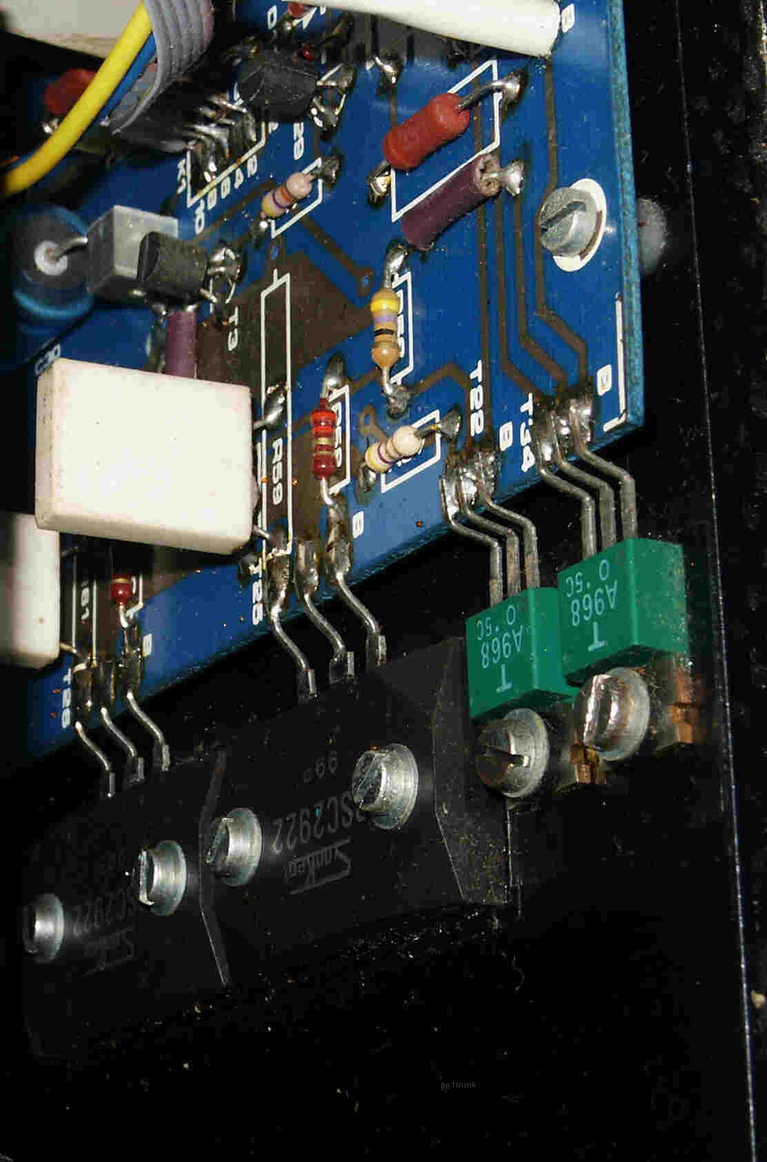
The right channel power transistors with the drivers and heatsink.
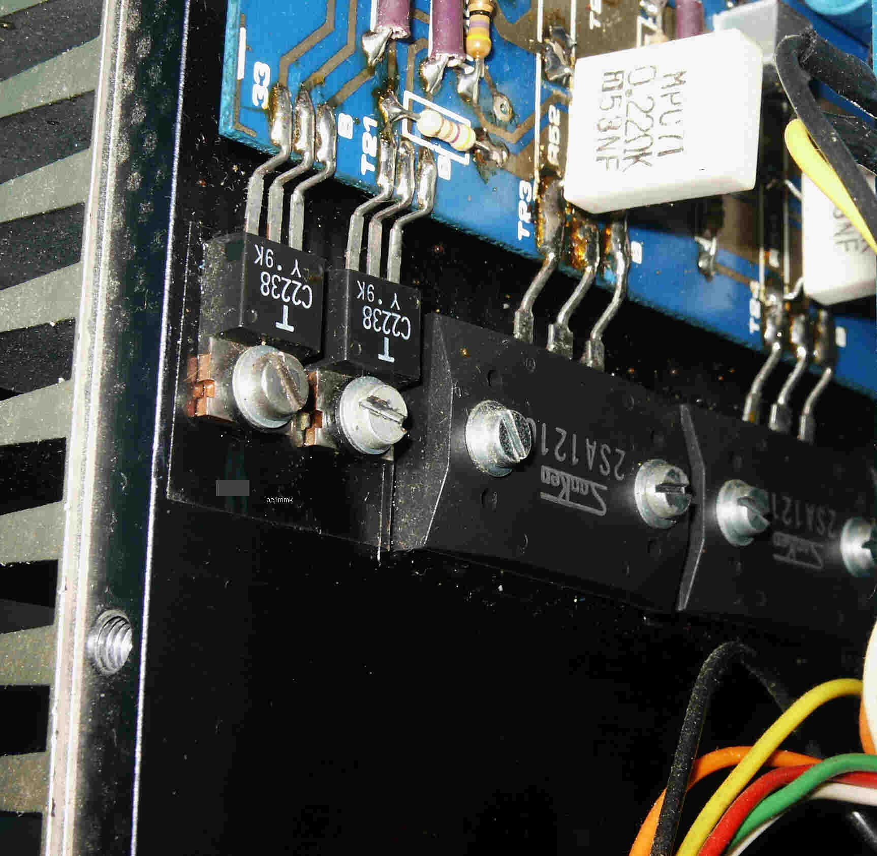
The left channel power section.
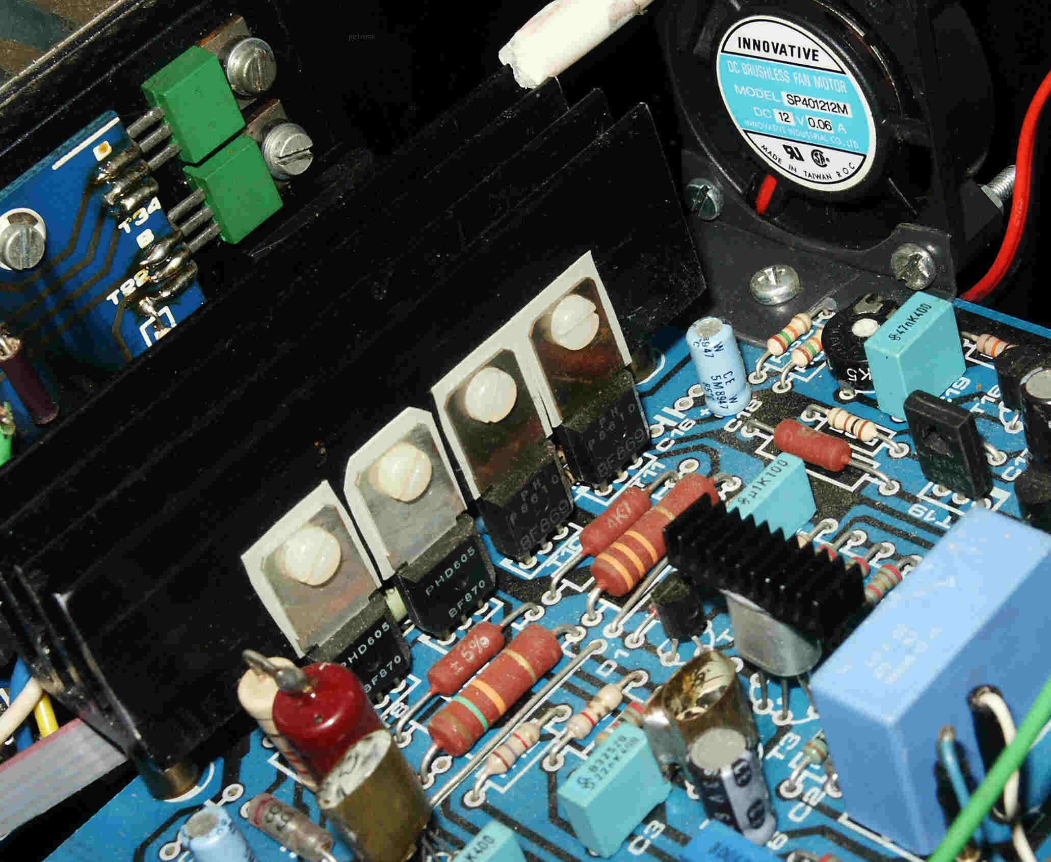
The pre-stage with high voltage diff-amp and on the background a part of the regulated power supply of the pre-stage.
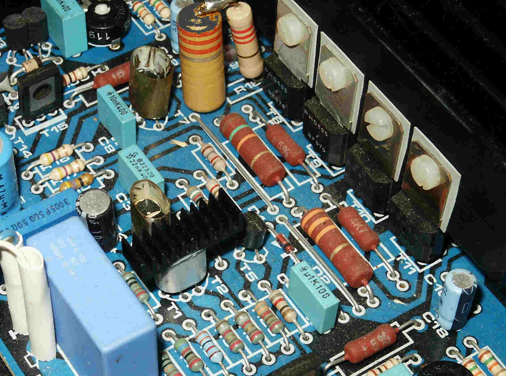
Pre-stage and input stage of the right channel. Note that the diff-amps are all put into copper heat compensation units to eliminate temperature drift.
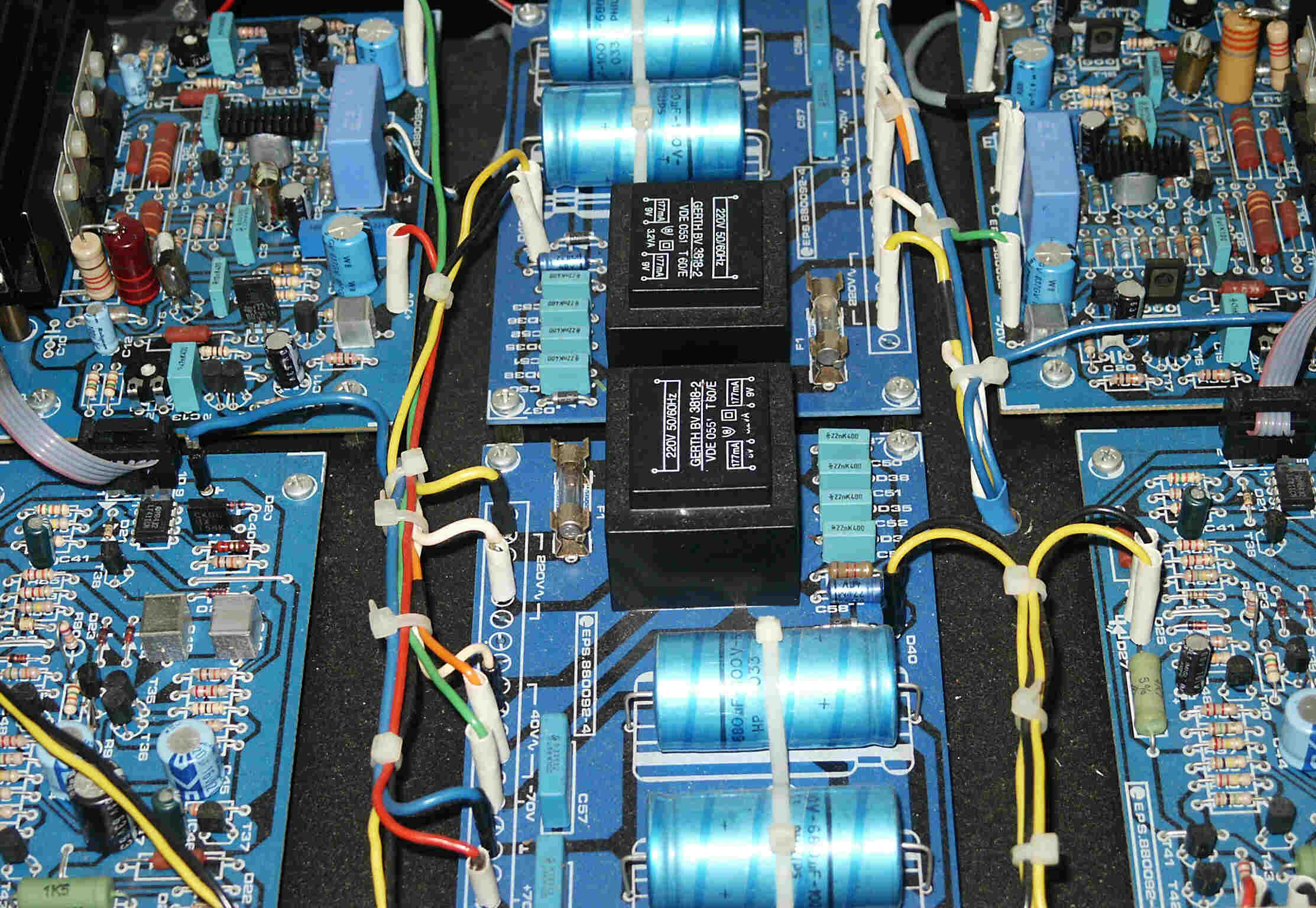
The power supply stage in the middle.
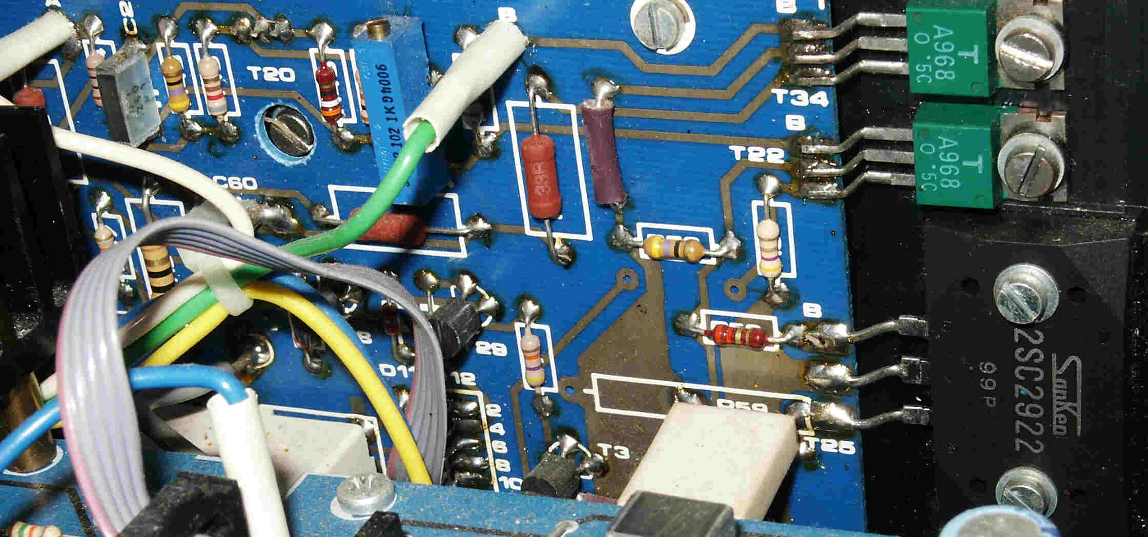
Another picture of how the power transistors are directly mounted on the pcb.
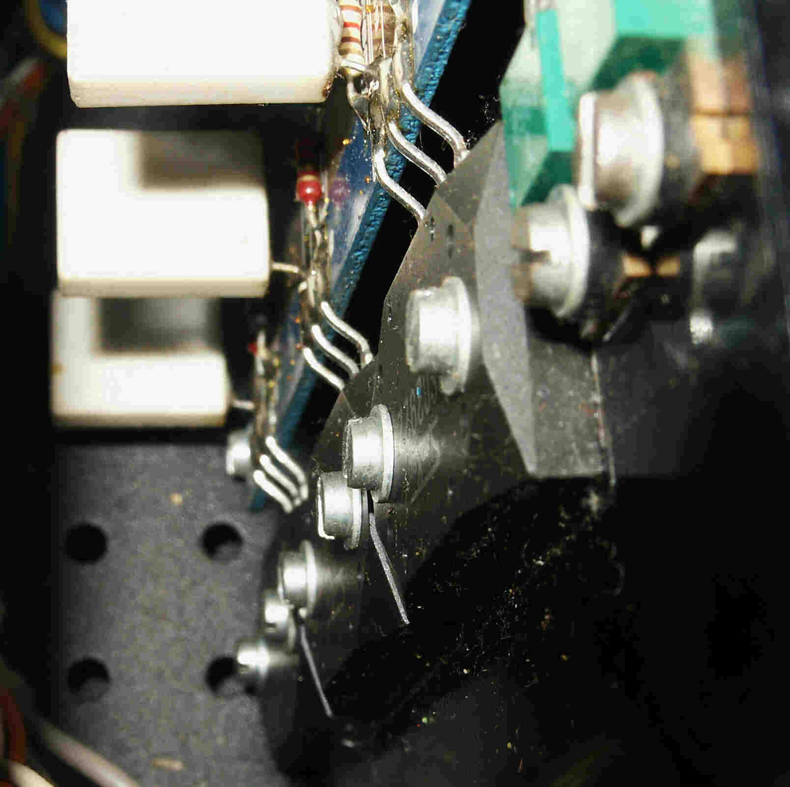
Heatsinking 6 output and 4 driver transistors.
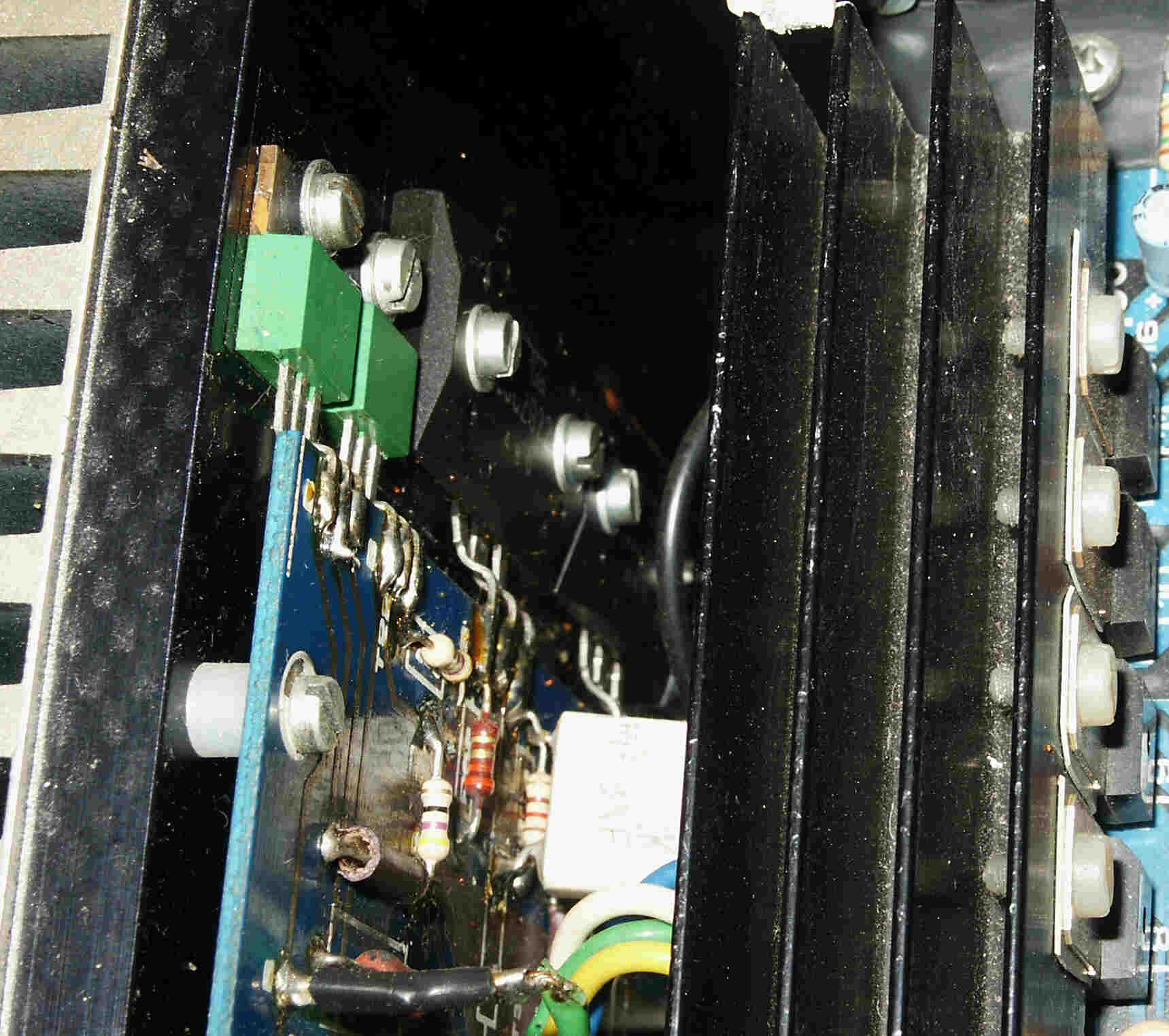
The protection and powersupply pcb.
The pcb's are made by a professional pcb company and the pcb-designs were made by Laurent Martin for Elektor.
Click here to goto the homepage of this ampifier section
©Hans Hilberink - PE1MMK ® 15-06-2006.